Refractory data sheets usually list a similar set of properties: chemical composition, cold crushing strength (CCS), permanent linear change (PLC), thermal conductivity, apparent porosity and bulk density. Engineers compare them in tables, procurement teams use them to rank suppliers, and maintenance departments reach for them when planning repairs.
There is just one problem – these parameters are easily misinterpreted. The temptation to reach for simple generalisations and blanket assumptions is strong. Unfortunately, a higher CCS does not mean a better refractory. A lower porosity is not always an advantage. And a thermal conductivity measured in the laboratory can tell you very little about how the material will actually behave inside your furnace.
In this guide we break down what each of these four key properties actually says about how a refractory performs – and, just as importantly, what it does not say. If you design or maintain refractory linings, understanding these nuances will help you avoid costly mistakes.
Porosity: the property that governs everything else
If you could look at only one number on a data sheet, porosity would tell you the most. That is because it directly influences corrosion resistance, thermal shock behaviour, permeability, thermal conductivity and mechanical strength – in other words, almost every other property that matters in service.
What this number actually means
Apparent porosity (AP) measures the volume of open, interconnected pores as a percentage of the total volume. These are the pores that liquids and gases can enter. The sum of open and closed pores is described by the total porosity.
This distinction matters. Two bricks with identical apparent porosity but different total porosity will behave differently under thermal shock – partly because closed pores arrest cracks without at the same time creating pathways for corrosive infiltration.
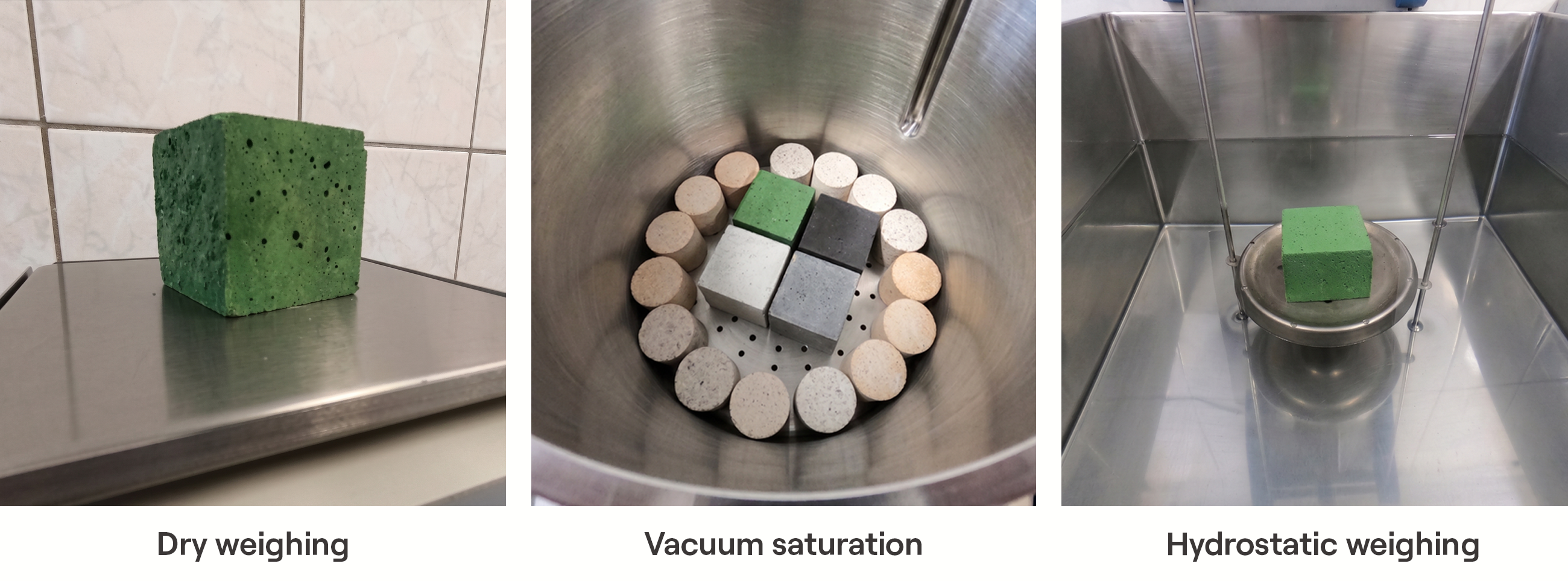
Measurement of apparent porosity by the Archimedes method.
How porosity controls corrosion resistance
Open pores act as flow paths – you can picture them as a network of channels through which molten slag, glass or metal penetrate deep into the refractory. The deeper the penetration, the more destructive the corrosion, because the reactions occur not only at the working surface but throughout the infiltration zone.
But volume alone is not everything. Pore size distribution is equally critical. A material with fine pores (below 1–5 µm) resists infiltration far more effectively than a material with the same total porosity but coarser pores. The reason is capillary pressure – finer pores generate greater resistance to liquid ingress.
The practical consequences are significant. The critical pore diameters below which specific alloys cannot penetrate are approximately:
| Melt type | Critical pore diameter |
|---|---|
| Steel | ~30 µm |
| Cast iron | ~5 µm |
| Aluminum | ~0.5 µm |
This explains why applications in contact with aluminium require exceptionally fine-pored, low-porosity materials, whereas steelmaking applications tolerate a somewhat coarser structure.
The porosity–thermal shock trade-off
And here it becomes counter-intuitive. Under certain conditions, higher porosity can improve thermal shock resistance – exactly the opposite of what happens with corrosion resistance.
Pores act as crack stoppers through several mechanisms:
Crack-tip blunting. When a propagating microcrack meets a pore, the sharp crack tip – an extreme stress concentrator – is replaced by the rounded surface of the pore. This can drastically reduce the stress intensity and arrest further crack growth.
Crack deflection and branching. Pores force cracks to change direction or split into many smaller branches. Each deflection absorbs additional energy, increasing the material’s effective toughness.
Lower modulus of elasticity. A more porous structure is less rigid. Lower stiffness means lower thermal stresses for a given temperature change – the material can „flex” rather than crack.
Less stored elastic energy. Dense, high-strength refractories store large amounts of elastic strain energy during heating. This stored energy is the driving force behind rapid, destructive crack propagation. Porosity reduces that energy reserve.
It is precisely for this reason that insulating bricks (with 45–85% porosity) are practically immune to thermal shock damage, whereas dense, low-porosity materials can fail catastrophically after a single rapid temperature change.
The design trade-off
Every engineer working with refractories faces the same dilemma: lower porosity for corrosion resistance, or higher porosity for thermal shock resistance? The answer depends entirely on which wear mechanism dominates in your specific application.
In the burning zone of a cement kiln, where the main threat is chemical attack by alkali-rich liquid clinker, you want low porosity. In a steel ladle, which goes through rapid thermal cycles with every tap, you need enough porosity to survive the shock. Getting this trade-off wrong is one of the most common and most expensive mistakes in material selection.
Cold crushing strength (CCS): the most commonly misunderstood number on the data sheet
CCS is the maximum compressive load a refractory sample can withstand at room temperature before it fails. It is also, arguably, the most overvalued property in refractory specification.
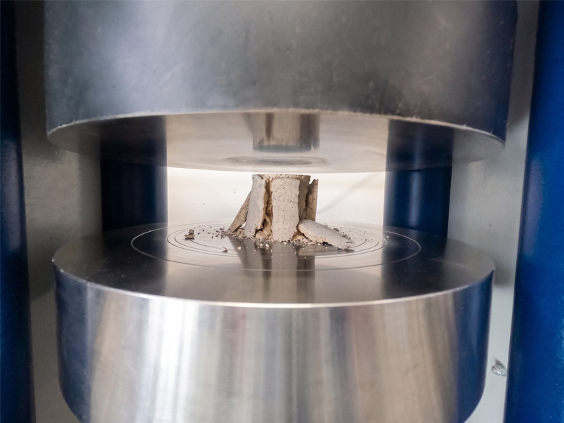
Cold crushing strength (CCS) test.
What CCS actually tells you
CCS is first and foremost a quality-control tool. It indicates whether the material was fired at the right temperature during production, whether sintering proceeded correctly and whether the bonding system (hydraulic, chemical or ceramic) developed as intended.
In other words, it speaks to production consistency. A batch of bricks with CCS significantly below specification probably has a manufacturing problem. That is genuinely valuable information.
Why higher CCS doesn’t mean “better”
A persistent myth lingers in the industry that a refractory with a higher CCS is inherently better. This is misleading, and in some cases the opposite is true.
The fundamental problem: CCS is measured at ambient temperature. A refractory’s working environment is 800 °C, 1200 °C, 1500 °C or more. How a material behaves at room temperature may have little in common with how it behaves at operating temperature.
Specifically:
An excessive CCS may indicate a high glassy-phase content. Glass is strong and rigid at room temperature – which gives impressive CCS values. But glass gradually softens as temperature rises. A refractory rich in glassy phase may show excellent CCS at 20 °C yet deform readily under load at 1100 °C. The result is creep – a slow, irreversible dimensional change under sustained stress at high temperature, which can destroy the lining geometry and close critical clearances.
A very high CCS often correlates with brittleness. Extremely strong, rigid materials have a limited ability to accommodate thermal and mechanical stresses. During cyclic temperature changes they are prone to destructive cracking and spalling rather than controlled microcracking.
CCS says nothing about hot strength. For predicting mechanical performance in service, hot modulus of rupture (HMOR) and refractoriness under load (RUL) are far more informative. HMOR measures flexural strength at the actual operating temperature. RUL measures resistance to deformation under constant load at rising temperature. Both give direct insight into whether the material will retain its structural integrity where it actually matters – inside the furnace, at high temperature.
What CCS is genuinely useful for
CCS reliably predicts whether a refractory will survive the mechanical stresses of transport, handling and installation. A brick needs enough compressive strength to withstand loads on the pallet, forklift impacts and the forces at play during bricklaying. For this purpose, CCS is an appropriate and necessary specification.
Practical takeaway
When reviewing a data sheet, resist the instinct to equate a higher CCS with the material’s mechanical resistance in service. Instead, ask: what are the dominant loads in my specific application – compressive, thermal, chemical? Then look at the properties that directly measure resistance to those loads. CCS tells you whether the material was manufactured correctly. It does not tell you how long your lining will last.
Permanent Linear Change: predicting whether your joints will hold
Permanent linear change (PLC) measures the irreversible dimensional change that occurs after a refractory is heated to a given temperature and cooled back to ambient.
What PLC tells you about production
PLC shows whether the refractory was brought to a stable equilibrium state during production. If a brick was fired at a temperature lower than its target operating temperature, the chemical reactions and sintering processes that did not finish in the manufacturer’s kiln will continue inside your furnace.
This continued reaction means the material is still changing dimensions while it is already in your lining – and once it cools, it will not return to its original size.
PLC is not the same as thermal expansion
This is a critical distinction, and one that even experienced engineers confuse.
Reversible thermal expansion (RTE) is the reversible change in a product’s dimensions caused by rising temperature. It is a purely physical process: atoms vibrate more intensely at higher temperatures, the crystal lattice expands, the material grows. As it cools, it returns to its original dimensions.
Permanent linear change (PLC) describes the change that will be irreversible – the material can either shrink or expand. It is the permanent mark that exposure to high temperature leaves in the material’s structure. PLC results from:
- further sintering and the elimination of pores (causes shrinkage),
- phase transformations and chemical reactions at operating temperature, e.g. the formation of mullite or spinel (can cause expansion or shrinkage depending on the reaction),
- decomposition of binders or the release of gases.
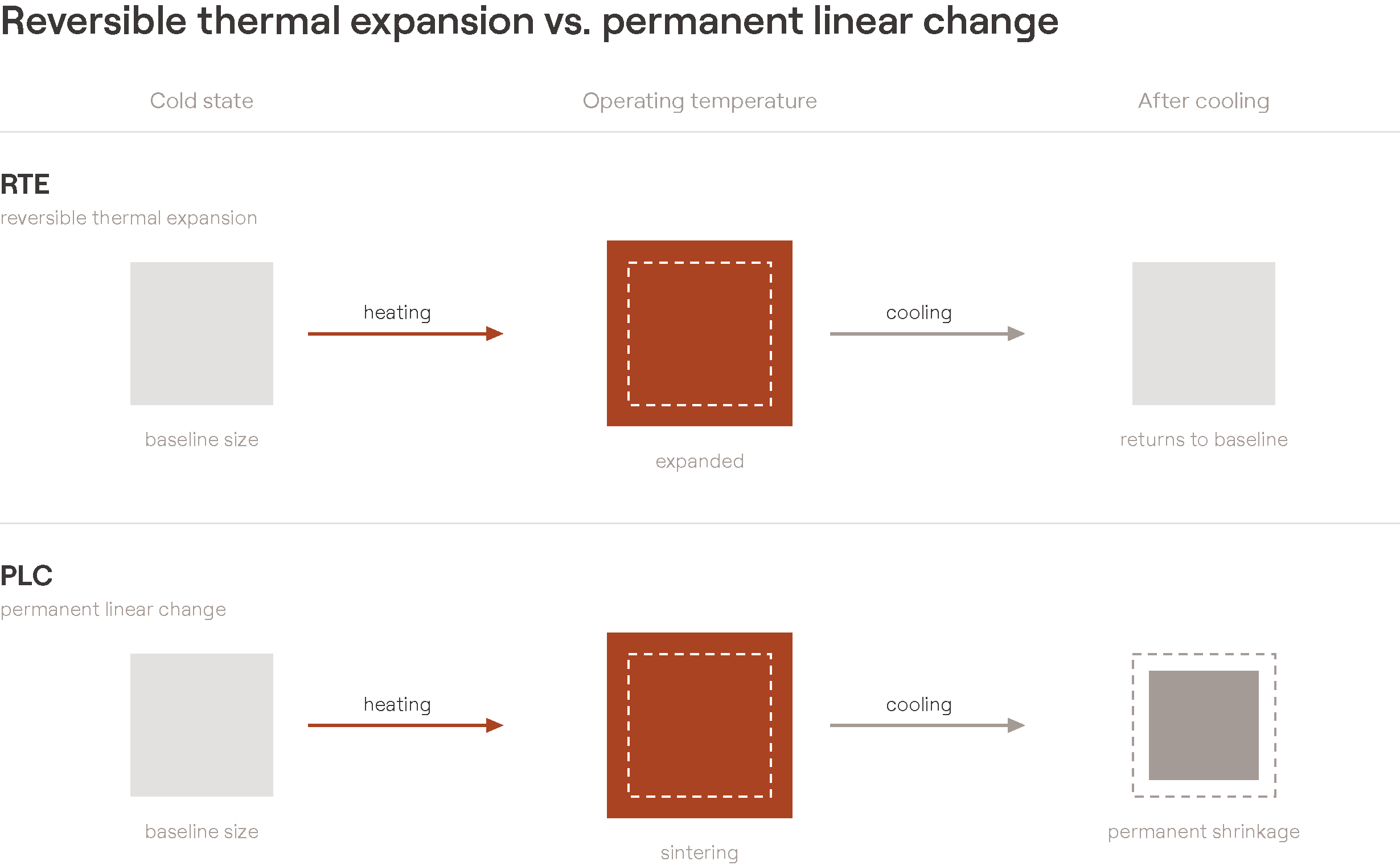
Reversible thermal expansion (RTE) vs. permanent linear change (PLC)
One way to think about it: RTE is the material „breathing” with temperature – it always returns to its starting point. PLC is a permanent change in the material’s „DNA” after exposure to operating conditions.
Why PLC matters for lining integrity
It is worth starting from the fact that permanent shrinkage or expansion is a natural feature of refractory materials. They are not a problem if they occur to a small degree – they can become one when their magnitude is large.
Negative PLC (shrinkage). When a refractory permanently shrinks in service, the joints open up. Open joints allow flames, hot gases or corrosive liquids to bypass the working lining and attack the backup layers or the steel shell. In extreme cases this leads to shell overheating, accelerated degradation of the backup layers and, consequently, unplanned repairs.
Positive PLC (expansion) is sometimes engineered deliberately. In vessel linings such as steel ladles, controlled positive PLC creates a tight clamping ring as the bricks grow slightly during the first heating cycles. This self-tightening effect seals the joints and prevents metal penetration – a critical requirement in steelmaking. Some materials based on „swelling clays” or spinel-forming compositions are specially designed for this purpose.
How PLC affects furnace design
The interplay of RTE and PLC drives several key design decisions:
Expansion joints must accommodate RTE – the reversible thermal „breathing” of the lining during every operating cycle. Undersized joints lead to compressive damage, spalling and, in extreme cases, deformation of the steel shell. Oversized joints, on the other hand, allow hot gases to break through the lining.
Long-term joint integrity depends on PLC. Even if the expansion joints are well designed for RTE, excessive negative PLC will gradually open the working joints over the whole campaign, degrading lining performance over time.
Mortar joints play a compensating role. A properly selected mortar is slightly compressible, absorbing up to half of the reversible thermal expansion of the brickwork. In large-scale structures such as coke oven batteries – where conventional expansion joints are impractical – highly plastic mortars are used to accommodate the full thermal expansion of the wall.
Practical takeaway
When specifying refractories, always check that PLC was measured at a temperature corresponding to your actual operating conditions. PLC data at 1000 °C is useless if your application runs at 1500 °C. And remember – a small, controlled positive PLC can be an advantage in some vessel linings, whereas negative PLC is almost always undesirable.
Thermal Conductivity: the number that changes with everything
Thermal conductivity defines the rate of heat flow through a material. In refractory engineering it determines how effectively a lining works as an insulator (to save energy and protect the shell) or as a conductor (to remove heat and cool the working face).
What this number tells you
At its simplest, thermal conductivity is the basis of every heat balance in furnace design. It determines lining thickness, shell temperature, heat losses and energy consumption. If this value is wrong, the entire thermal design falls apart.
But there is a challenge: thermal conductivity is not a material constant. It changes with temperature, atmosphere and measurement method – sometimes drastically.
How temperature changes everything
Dense and porous refractories respond to temperature in exactly opposite ways:
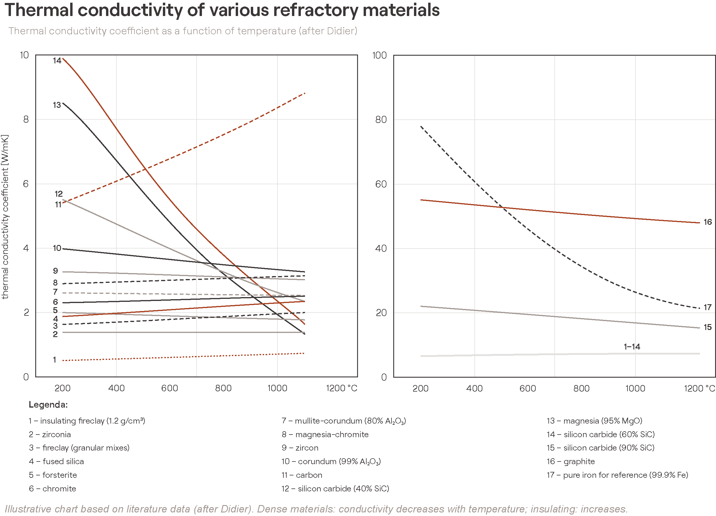
Dense materials: conductivity decreases as temperature rises. The mechanism is phonon scattering – as atoms vibrate more intensely at higher temperatures, they interfere more strongly with heat conduction through the crystal lattice.
Insulating and lightweight materials: conductivity increases with temperature. At high temperatures, radiation across the large internal pores becomes the dominant heat-transfer mechanism, outweighing conduction through the solid phase that dominates at lower temperatures.
This crossover behaviour means that an insulating material performing well at 600 °C may provide significantly weaker insulation at 1200 °C – a fact that must be taken into account when designing multi-layer linings.
The atmosphere effect that most engineers overlook
Thermal conductivity depends not only on the solid material but also on the gas filling its pores. This is especially significant for porous materials.
An alumina-silicate refractory in a hydrogen atmosphere has a significantly higher thermal conductivity than the same material in air. The thermal conductivity of hydrogen is roughly 7× that of nitrogen. In applications where hydrogen-rich gases are present – some heat-treatment furnaces, direct reduction in steelmaking – standard conductivity data measured in air will significantly underestimate the actual heat losses.
Measuring thermal conductivity – a common pitfall
There are two standard methods for measuring thermal conductivity, and they can give results differing by 15–25%:
| Method | Operating principle | Typical use |
| Calorimetric (steady-state) | Measures heat flow once thermal equilibrium is reached | Reference method for furnace design; gives an averaged value across the temperature gradient |
| Hot-wire (transient) | Measures the temperature response to a rapid thermal pulse | Faster measurement; gives point values at specific temperatures |
The discrepancy stems from fundamental differences in how these methods work. The calorimeter measures conductivity as an average across the temperature gradient inside the sample, whereas the hot wire records the value at a specific temperature. In addition, the hot-wire method conducts heat radially and the calorimeter linearly – for anisotropic materials this yields different results.
In practice, furnace designers usually prefer data from the calorimetric (steady-state) method. When only hot-wire data is available, correction factors of 0.7–0.8 are commonly applied to match design expectations.
Practical consequences for lining design
When specifying refractories for a new lining or assessing insulation effectiveness:
Always check the measurement method. Data sheets do not always state it. If conductivity values look surprisingly low for a dense material, they may come from a steady-state measurement. If they look high for an insulating material, they may come from the hot-wire method.
Use temperature-specific values. A single conductivity figure at 1000 °C is insufficient for a lining with a gradient from 1500 °C at the working face to 150 °C at the shell. Multi-point data across the whole operating range is essential.
Account for the atmosphere. If your process involves reducing gases, hydrogen or water vapour, standard data measured in air may underestimate the actual heat losses.
Consider the ageing effect. Slag infiltration, sintering and chemical reactions during service change the pore structure – and therefore the conductivity. A lining’s thermal behaviour in the first month can differ significantly from its behaviour after a year.
How these four properties interact
No refractory property exists in isolation. The four properties discussed here form an interconnected system, and understanding those connections is what separates effective material selection from data sheet comparison.
Porosity is the common denominator
Porosity directly influences all three of the other properties:
| As porosity increases… | CCS | PLC (tendency) | Thermal conductivity |
| Effect | Decreases | Tendency to shrink may increase (more volume to sinter) | Decreases (better insulation) |
| Gain | Better thermal shock resistance | — | Better energy efficiency |
| Loss | Lower mechanical strength | Potential joint instability | Weaker conductive cooling of the hot face |
The CCS and thermal shock paradox
A very high CCS usually means very low porosity and high stiffness, and both of these factors reduce thermal shock resistance. The strongest material on the shelf may at the same time be the most vulnerable to rapid temperature changes. When cyclic thermal loads are part of the operating reality, a moderate CCS is often the wiser specification.
The interdependence of PLC and conductivity
When a material undergoes a permanent dimensional change in service – whether sintering (shrinkage) or a phase transformation (expansion) – its pore structure changes. Sintering reduces porosity, which increases thermal conductivity. The lining becomes a less effective insulator over time. This is why thermographic data from the first year of a campaign should not be used to predict shell temperature in the third year without accounting for this progression.
Key takeaways
- Porosity is the single most informative property – it can be an indicator of corrosion resistance, thermal shock behaviour and thermal performance. But pore size distribution matters just as much as total pore volume.
- CCS is an indicator of manufacturing quality, not a predictor of in-service performance. A high CCS can signal an excessive glassy phase and brittleness. To assess strength in service, use HMOR and RUL.
- PLC shows whether the material has reached dimensional equilibrium. Always verify that the test temperatures match your operating conditions. Negative PLC opens joints; controlled positive PLC can seal them.
- Thermal conductivity changes with temperature, atmosphere, infiltration and the age of the material – it is never a single, fixed number.
- No property should be evaluated in isolation. Material selection is about finding the right balance between competing requirements – and that balance is different for every application.
Frequently asked questions
Does a higher CCS mean a better refractory?
No. CCS (cold crushing strength) is primarily an indicator of manufacturing quality, measured at room temperature. A very high CCS can in fact signal an excess of glassy phase and brittleness, which worsens thermal shock resistance. HMOR and RUL say far more about how the material performs at high temperature.
What is the difference between apparent and total porosity?
Apparent porosity (AP) covers only the pores that are interconnected and open to the surface – these are what liquids and gases penetrate. Total porosity is the sum of open and closed pores. Two bricks with the same apparent porosity but different total porosity will behave differently under thermal shock, because closed pores arrest cracks.
Why is data-sheet thermal conductivity sometimes misleading?
Because it is not a material constant. It changes with temperature (decreasing in dense materials, increasing in insulating ones), with atmosphere (hydrogen conducts heat about 7× better than nitrogen) and with measurement method (results can differ by 15–25%). A single figure without stated conditions has limited design value.
What is the difference between PLC and thermal expansion?
Thermal expansion (RTE) is reversible – the material grows on heating and returns to size after cooling. PLC (permanent linear change) is irreversible – a permanent shrinkage or expansion that remains in the structure after exposure to high temperature. Expansion joints are designed for RTE, while joint integrity over time depends on PLC.
Need help interpreting the values on a data sheet for your specific application? PCO’s technical team will help you assess a material’s properties in the context of your operating conditions, wear mechanisms and performance goals.