Bottom Pouring Refractories: A Bauxite Hollow-Ware Case Study In brief: A leading European special-steel and forging mill (~120,000 t/year) had three problems at once in its bottom-pouring set: inclusions and cracks in the ingot, impurity pickup from the refractory, and a real breakout risk at the joints. PCO redesigned the set around the bauxite grade ALUTEX B80Lc (>80% Al₂O₃, low Fe₂O₃), with long tongue-and-groove connections on every joint and equalised tolerances across all shapes. The result: zero breakouts since implementation, smooth, clean runner channels, and less risk of impurities and micro-inclusions.
Roughly 97.5% of the world’s steel is continuously cast: it leaves the caster as slabs, blooms and billets and goes on to become coil, rails and bars. The remaining share is still cast the older way — poured into individual ingot moulds. Not out of habit. Heavy forging ingots and special, tool and high-alloy grades keep to the ingot route because it delivers the internal cleanliness and surface quality these products need. These ingots are bottom-poured.
The key to bottom pouring is the casting system: a set of refractory ceramic shapes packed into a steel casing and a casting plate, connected to the moulds. This is the hollow ware — the funnel, the guide tubes, the central block and the runner bricks — and every tonne of the heat flows through it on its way to the mould. The ingot is only as good as the ceramic the steel flowed through. The set has to do two things at once: withstand the casting conditions — roughly 1600 °C and up to an hour of flowing metal under a rising ferrostatic head — and give nothing up to the steel, because every particle the channels shed ends up in the ingot as a defect.
This article first walks through why refractory selection for the hollow ware matters so much — the wear mechanisms, the trade-offs, and the business consequences. Then it presents a real field case: a European special-steel and forging mill that moved its bottom-pouring set from a sintered mullite-type material to a low-iron bauxite grade and measured the difference in ingot cleanliness, refractory wear, and breakout risk.
If you specify refractories for an ingot shop, plan its shutdowns, or evaluate suppliers for hollow-ware sets, this one is written for you.
How bottom pouring actually works
In bottom (or “uphill”) teeming, liquid steel is not poured directly into the top of the mould. It pours from the ladle into a funnel, drops down a column of vertical guide tubes, and then travels horizontally and upward through a network of ceramic channels that fill each mould quietly from the base.
The flow path is a chain of refractory shapes — the assembled set is the hollow ware (sometimes called an ingot set), and the solidified steel skeleton left inside it after casting is the “bone” (or spider):
- Funnel: the receiving cone at the top of the set — the shape the steel stream from the ladle nozzle is actually poured into.
- Guide tubes (channel bricks): the vertical tubes below the funnel through which the steel flows down. They are stacked with tongue-and-groove ends for precise registry.
- Central block (king brick): the distribution hub at the bottom of the guide-tube column, with several off-takes that let one column feed multiple moulds at once.
- Runner bricks: the horizontal channels that carry steel from the central block to the base of each mould, ending in an end block under the mould stool.
Because the mould fills from below, the metal surface rises smoothly instead of splashing. That is the whole point: bottom pouring gives a superior ingot surface with far less reoxidation than top pouring, which is why it dominates in forging-grade, tool, and special steels where surface and internal quality are non-negotiable. It also lets a shop fill several ingots from a single teem — good for productivity, but it means one weak runner can spoil more than one ingot.
Why the hollow ware is where refractory choice bites
The hollow ware sees a brutal combination of conditions in a very short time. The steel arrives at roughly 1600–1650 °C (2910–3000 °F), moving fast and turbulent, and the channels must hold a rising ferrostatic head for the length of the teem — often close to an hour for large ingots — without softening or leaking. On top of that, the components go from ambient to full heat in seconds when the pour begins, so thermal shock on that first surge is a real failure mode.
Silica reduction by dissolved aluminium. In aluminium-killed steels, dissolved [Al] reduces silica in the refractory: SiO₂ + [Al] → Al₂O₃ + [Si]. This eats the refractory surface and generates large exogenous alumina inclusions that end up in the steel. It is the single biggest reason to keep free silica low in hollow ware for high-cleanliness grades.
Manganese oxide fluxing. MnO is a strong basic flux. It reacts with SiO₂ in the ceramic to form low-melting manganese silicates, which soften and are then physically washed away in the turbulent zones — exposing fresh refractory to further attack. High-manganese grades are especially aggressive.
Iron-oxide wetting. Fe₂O₃- and FeO-bearing phases wet the ceramic surface, aggravating both erosion and reoxidation of the steel.
For the person paying the bills, this translates into three concrete business risks:
The scale of the problem is well documented: in killed steels, roughly 60% of exogenous (macro) inclusions are attributed to chemical attack and fluxing of refractories — and erosion-derived inclusions tend to be larger, and therefore more harmful, than those from slag entrainment. Erosion concentrates wherever flow is turbulent, which is why the literature recommends keeping flow velocities in runner systems low, especially during the critical early stage of the teem.
- Dirty steel → rejects. Macro-inclusions and reoxidation products cause internal defects that show up in ultrasonic testing or during forging — scrapped or reworked ingots at full added-value cost.
- Breakouts → lost heats and safety events. A cracked runner or a leaking joint under ferrostatic pressure can breach the set mid-teem: a lost heat, an unplanned clean-up, and a genuine safety hazard.
- Refractory pickup → downgrade. Material torn from the lining becomes an exogenous inclusion in its own right — the opposite of the “zero pickup” that clean-steel customers demand.
The material menu for hollow ware
Refractory selection for the hollow ware is essentially a walk up the alumina–silica system, trading cost for chemical resistance and cleanliness.
| Grade family |
Typical Al₂O₃ |
Character in the hollow ware |
Best fit |
| Fireclay |
30–42% |
Cheapest, tolerant of thermal shock, but high SiO₂ reacts readily with [Al] and MnO |
Simple / acid grades, small ingots, short teems |
| Sintered mullite |
~72% (mullite phase) |
Low thermal expansion → very good thermal shock and creep resistance; less corrosion and infiltration than fireclay |
Higher grades needing good surface quality |
| Fused mullite |
~72% (mullite phase) |
Very low thermal expansion → outstanding thermal shock resistance; better corrosion resistance and less infiltration than sintered mullite or fireclay — but expensive |
Higher grades needing excellent surface quality, where budget allows |
| Bauxite (fired or chemically bonded) |
>80% |
Higher alumina, lower free silica than mullite; low-iron grades give clean-steel performance and stronger breakout protection |
Aggressive / zero-pickup grades, big ingots, high ferrostatic pressure, long teems |
Two nuances matter more than the headline alumina figure.
First, mineralogy beats raw chemistry. What resists erosion is the stability of the bond phase — the mullite matrix, the low-silica glass — not simply the total Al₂O₃ percentage. A high-alumina brick with an unstable, silica-rich bond can erode faster than a lower-alumina one with a clean matrix.
Second, the bond system changes how the shape behaves during the pour. Bauxite hollow ware is often chemically (phosphate) bonded rather than high-fired. Phosphate bonding gives the shape excellent handling strength, tight dimensional tolerances, and high abrasion resistance against the flowing stream — all valuable for a precisely registered tongue-and-groove set.
How to evaluate hollow-ware performance
Engineers judge hollow ware on the bench and on the casting floor, and the two have to agree.
On the bench, the key numbers are apparent porosity and bulk density (lower porosity resists metal infiltration, though some porosity is deliberately accepted for thermal shock tolerance and to insulate against premature freezing in the runners), refractoriness under load (RUL — will the runner hold its shape under the ferrostatic head?), permanent linear change (PLC — a slight positive value is often preferred, because a shape that expands a little keeps the joints tight), and thermal-shock cycles.
But the ultimate verdict is written on the bone — the solidified steel skeleton stripped from the set after casting. A used runner set is a post-mortem sample, and experienced people read it directly:
- Is the bone surface smooth and clean, with no refractory adhering to the steel? That means low reaction and easy stripping.
- Does a section through the runner show infiltration without reaction — steel that soaked into the pores but left the matrix intact, with no weak phases or cracks?
- Do ingot cleanliness tests (inclusion counts, micro-inclusion ratings) improve?
Lab metrics plus a clean bone plus cleaner ingots — that combination is what “good” looks like. It is also exactly what the following case delivered.
Case study: low-iron bauxite hollow ware for 42CrMo4 forging ingots
The operation
A leading European special-steel producer and forging mill, casting roughly 120,000 tonnes per year, runs a bottom-pouring ingot route for alloy forging grades. The reference case is a 42CrMo4 heat — a chromium–molybdenum forging steel where internal cleanliness directly governs the value of the finished part.
| Parameter |
Value |
| Steel grade (reference) |
42CrMo4 |
| Casting temperature |
1630 °C |
| Ladle capacity |
50 t |
| Casting duration |
~1 hour |
| Ingot size |
800 kg |
Under these conditions — special steel, nearly an hour of metal contact — the runner is not a passive channel. It is an active source of inclusions, skull, and breakout risk, and three things in the set decide the outcome: material composition, shape tolerances, and the depth of the tongue-and-groove joints.
The initial situation: good intentions on bad joints
The shop had been running a sintered mullite-type hollow ware, and the symptoms were scattered across the whole process but pointed to one place — the ceramic:
- The material could not keep up with the steel. Mullite did not provide the corrosion and infiltration resistance this grade demands over an hour of contact.
- Defects travelled into the ingot. Non-metallic inclusions and cracks — some of them traceable to the refractory.
- The requirement was zero pickup. The ceramic must not contribute impurities (SiO₂, Al₂O₃ from the glassy phase) to clean-steel heats. It did.
- Breakouts lurked at the joints. The set used short tongue-and-groove connections with an undefined mix of tolerances between shapes. The components never assembled the same way twice — every build was a slightly different lottery of tightness under a full ferrostatic head.
One diagnosis, two fronts: a material mismatched to the steel, and joints too shallow to close the metal’s escape path.
The change
PCO rebuilt the set around ALUTEX B80Lc — its dedicated hollow-ware grade, engineered from a special composition of carefully selected low-iron bauxites (>80% Al₂O₃, deliberately low Fe₂O₃) — with two design changes made alongside the material switch:
- Long tongue-and-groove connections on all joints. Deeper registry lengthens the path metal would have to travel through the joint — simple geometry, a real drop in breakout risk.
- Equalised tolerances across every shape in the set, so funnel, guide tubes, central block, and runners assemble to a consistent, tight fit — repeatable instead of a lottery.
The grade itself is where the metallurgy is hidden. The raw-material base — a composition of selected bauxites with high alumina and minimal free silica — leaves the steel almost nothing to react with, while the deliberately low iron-oxide content removes a wetting and reoxidation source. On top of that sits a dedicated chemical bonding system, developed specifically for hollow ware: it locks the dense bauxite grains into an abrasion-resistant matrix that stands up to the flowing stream, holds tight dimensional tolerances shape after shape, and expands slightly on first heating — so the assembled joints grow tighter, not looser, at the exact moment the ferrostatic head arrives.
The material logic is the same as in any lining selection: the more aggressive the grade, the higher the cleanliness requirement, and the bigger the ingot, the higher you climb the alumina ladder (fireclay → mullite → bauxite). Higher alumina and lower free silica leave less SiO₂ available for [Al] and MnO attack; low iron oxide removes a wetting and reoxidation source and limits the low-melting phases that drive pickup.
Assembly on the casting plate
The set is assembled on the casting plate: the central block receives the stream from the guide tubes, and from it the runners radiate out to the end blocks under each mould. With equalised tolerances and the long tongue-and-groove, the shapes seat tightly and repeatably.
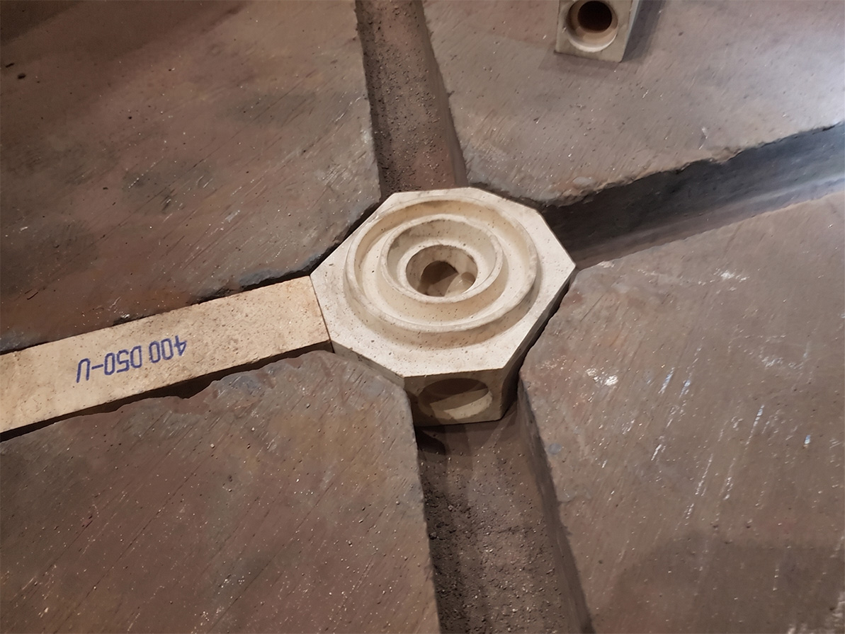
Central block (king brick) with a 400 mm runner during assembly in the casting plate.
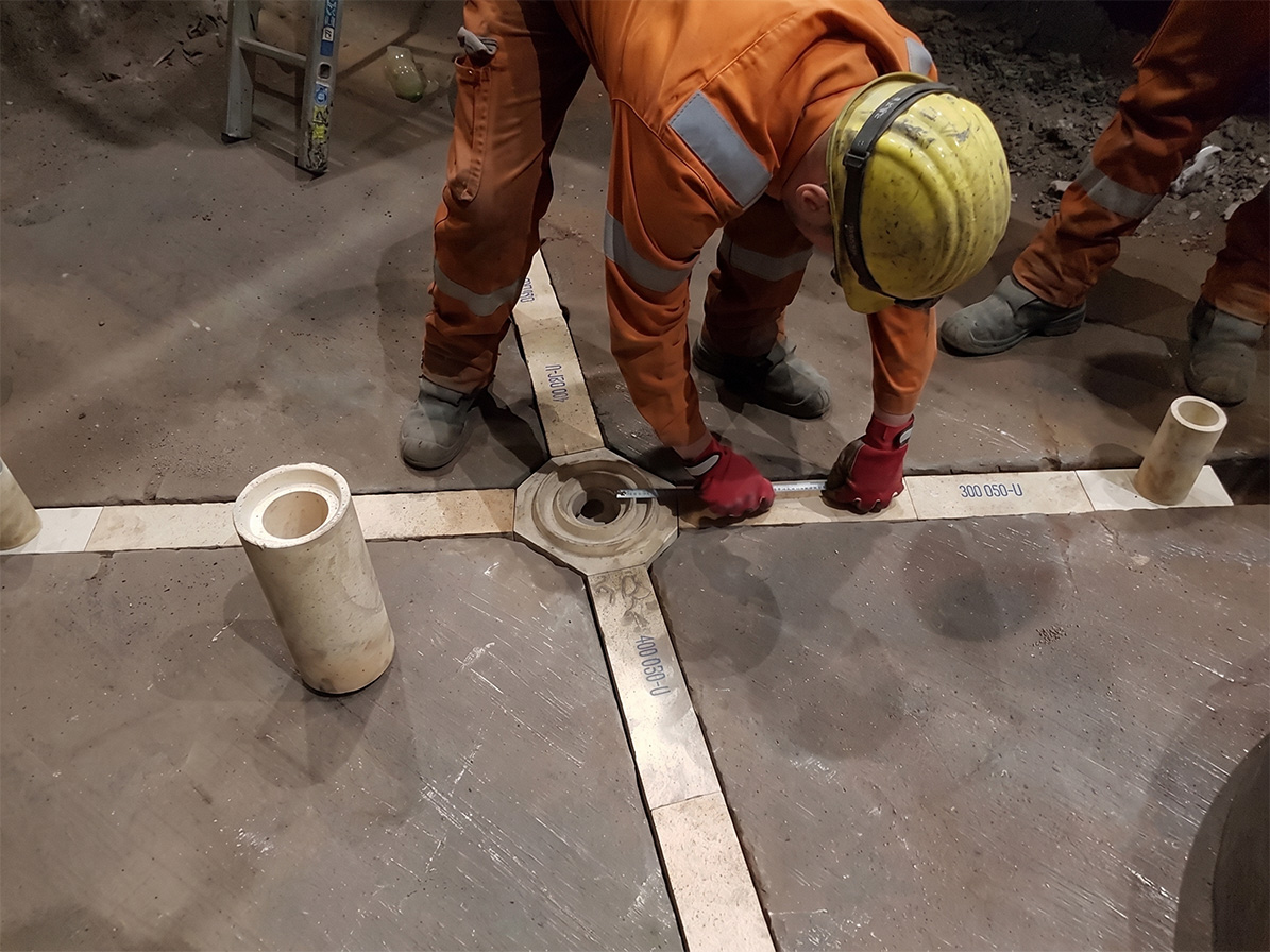
Set assembly: central block + 2 × 400 mm runners + end block on the casting plate
The results: the bones don’t lie
After casting, the most honest witness is the bone — the solidified steel stripped from the runner channels. Its surface is a direct imprint of what happened at the steel–ceramic interface. For the 42CrMo4 reference:
| What was assessed |
Outcome with the bauxite set |
| Breakout protection |
No breakouts since the material was introduced |
| Bone surface |
Smooth and clean; no refractory adhering to the steel; used bricks and skull strip off without a fight |
| Joints / connections |
Noticeably cleaner and tighter than the comparative solution |
| Runner cross-section |
Infiltration to about 50% of the wall, but no refractory wear, no weak phases, no cracks |
| Ingot cleanliness (lab) |
Fewer impurities and micro-inclusions in the tested ingots |
| Ingot quality |
Improved overall |
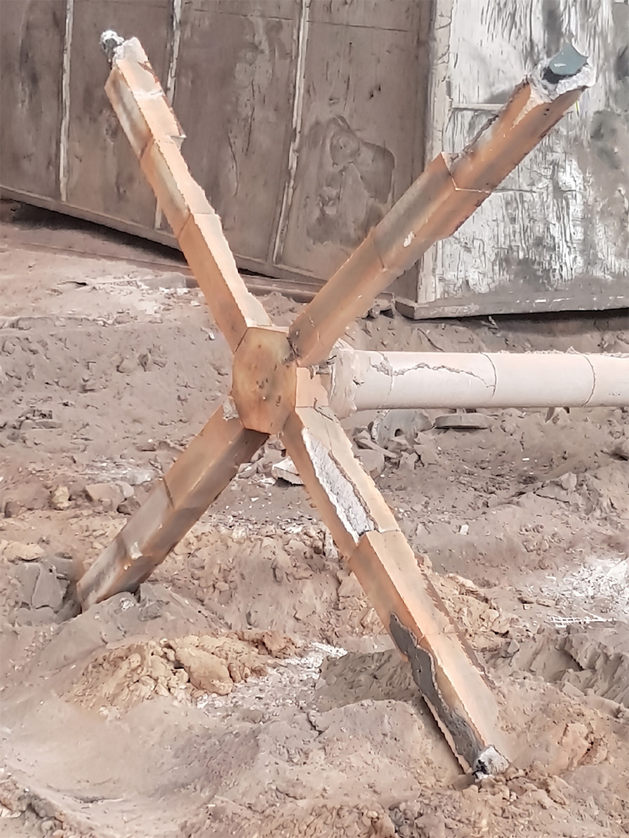
The complete steel skeleton (“bone”) on PCO shapes after casting.
The complete skeleton — even, uniform, with no growths or washouts. The set held its geometry through the entire teem.
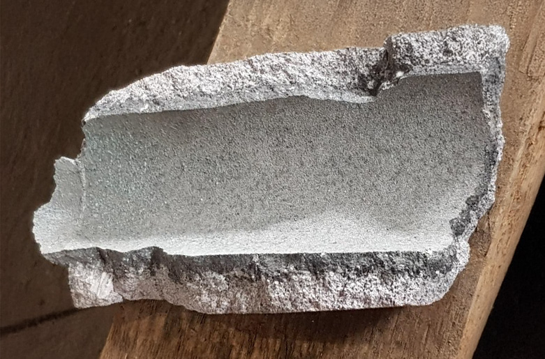
Contact surface between PCO refractory and bone, close to the central block
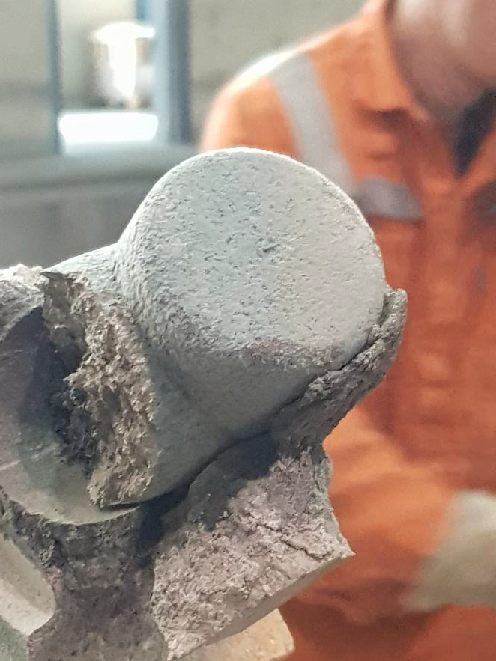
Bone surface at the end runner.
The cast skin is smooth and clean, and the refractory separates from it along a sharp, well-defined boundary. The steel did not bond with the ceramic — and took nothing from it.
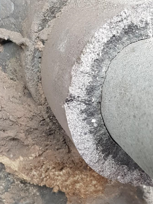
Section through the steel infiltration zone in a PCO runner.
The most telling result is that seemingly worrying line in the table: steel soaked roughly half-way into the runner wall — paired with the fact that it did no harm. The infiltrated zone is compact, with no cracking or crumbling. Controlled infiltration, not destruction. What matters is not whether the steel penetrated, but whether it broke anything: infiltration without reaction is acceptable; reaction is what tears refractory into the steel and eats the runner.
And here is the same location when the material cannot keep up with the steel — the comparative solution:

Bones from the comparative material.
Compare the surfaces. The comparative bones are uneven, rough, and locally thinner, with adhering refractory and rust-orange deposits along the surface. That is not cosmetics — it is the record of a reaction between ceramic and steel. A rough skin and adhering residue mean the material was being picked up by the metal and reacting with it; the discolouration is the product of that reaction — low-melting phases and oxides bound to the cast surface. Every such point on the ceramic–steel boundary is a potential non-metallic inclusion carried into the ingot. In other words: the bones show exactly what the laboratory later finds in the metal.
Why it worked
Every result traces back to the material and design logic. Cleaner steel came from the chemistry: bauxite at >80% Al₂O₃ carries less free silica than the previous mullite (~72%), and the grade’s low Fe₂O₃ removes a wetting and reoxidation source — so less of the SiO₂ + [Al] reaction, less MnO fluxing, fewer erosion-derived inclusions, and no measurable pickup. No breakouts came from the mechanical redesign plus the material’s behaviour: the long tongue-and-groove joints and equalised tolerances close the leak paths, while the chemical bond and the slight expansion on heating keep the assembled joints tight under the ferrostatic head. Easy stripping and a clean bone came from low reactivity — the refractory simply does not bond to the solidified steel.
None of this makes bauxite the universal answer. For simple or acid grades, small ingots, and short teems, fireclay or mullite may be perfectly adequate and more economical. The point of the case is narrower and more useful: for aggressive, clean-steel grades, big ingots, high ferrostatic pressure, and long casting times, a low-iron bauxite hollow ware buys measurable cleanliness and breakout margin that a silica-richer material cannot.
Key takeaways
- In bottom pouring, the hollow ware — not the furnace — is the refractory that decides ingot cleanliness and breakout risk; roughly 60% of exogenous inclusions in killed steel come from refractory attack.
- The wear is chemistry-driven: dissolved [Al] reduces SiO₂, MnO fluxes silica, and Fe₂O₃ wets and reoxidises. All three point the same way — lower free silica and lower iron oxide for clean grades.
- Fireclay → mullite → bauxite is a walk up chemical resistance and cleanliness. Match the grade to the steel, ingot size, and teem length rather than defaulting to the cheapest or the highest alumina.
- Joints are a failure mode of their own: deep tongue-and-groove registry and equalised tolerances are as much a part of breakout protection as the material.
- Read the bone: a smooth, clean, easily stripped skeleton with infiltration-but-no-reaction is the field signature of a well-matched material.
- In the case shown, switching a mullite set to low-iron bauxite (ALUTEX B80Lc) with a longer tongue-and-groove design delivered fewer micro-inclusions, zero breakouts, and clean stripping on 42CrMo4 forging ingots.
Frequently asked questions
Is mullite good enough for bottom pouring special steels?
For high cleanliness requirements and long casting times — choose bauxite. Higher Al₂O₃ gives greater resistance to corrosion and infiltration, and low Fe₂O₃ limits low-melting phases and impurity pickup. Mullite remains a sound choice for higher grades without such strict cleanliness demands; fireclay for simple steels and small ingots.
Does a longer tongue-and-groove joint really reduce breakouts?
Yes. Deeper registry lengthens the path metal would have to travel through the joint, and combined with equalised shape tolerances it produces repeatably tight connections. It is a physical closure of the escape path, not cosmetics.
Steel infiltrated ~50% of the runner wall — is that a reject?
Infiltration depth alone does not decide. If, despite the penetration, the material shows no wear, no weak phases, and no cracks, it is working in a controlled way. Judge the integrity of the structure, not the depth of soak.
How do I know the runner material is “dirtying” the steel?
From the ingot and from the bones: elevated inclusion and micro-inclusion counts in testing, refractory residue adhering to the channel surfaces, skull that is hard to remove. Bones that strip clean and smooth are the signal that the ceramic is not giving up impurities to the metal.
Related PCO solutions: PCO manufactures the full hollow-ware range for bottom-pouring sets — including chemically bonded Alutex B80Lc — and supports customers with set design (tongue-and-groove geometry and tolerancing), installation, and post-mortem bone analysis to pin down wear mechanisms on real used shapes, Technical support.
Struggling with inclusions, pickup, or breakouts in bottom pouring? PCO will help you select and design a hollow-ware set for your specific steel grade, ingot size, and casting time. Get in touch with our technical team
How to Select Refractory Material for an Industrial Furnace: A Practical Decision Framework Selecting a refractory material is not about finding the “best” product. It is about matching the material’s properties to the specific operating conditions of the furnace – thermal, chemical, mechanical, and structural. The goal is singular: to ensure predictable and economically justified lining service life.
In this article we present a five-phase decision framework that helps you move systematically from analysing the operating conditions to choosing the lining configuration. The framework is built on PCO’s many years of experience designing linings for the steel, cement, lime, power, and foundry industries.
Note: the recommendations presented here are for educational purposes only and cannot serve as a direct basis for designing a lining. Every application requires an individual and comprehensive analysis that accounts for the operating conditions, the geometry of the equipment, its service history, and the process requirements. If you need to select the right material for your equipment, consult our engineering department – the contact form is at the bottom of the page.
Phase I: Operating Conditions Audit — Where to Begin Refractory Material Selection
Before you start reviewing product data sheets, you must precisely describe the conditions under which the lining will operate. This is the absolute foundation of material selection – without it, every material decision is guesswork.
Thermal profile
Identify the maximum operating temperature and how long it is held (the so-called soaking period – the longest possible time the lining will be held at a given temperature). Take into account every possible extreme scenario here.
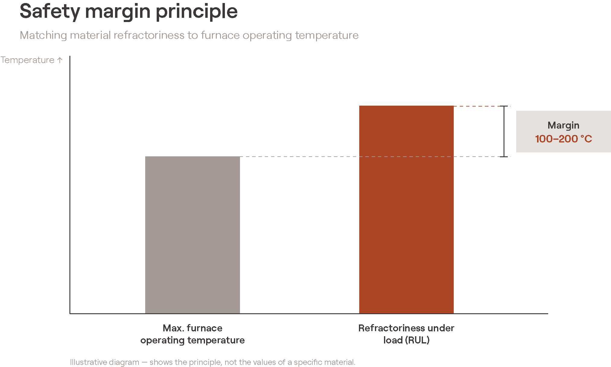
A practical rule of thumb: designers usually try to select a material whose refractoriness under load (ISO 1893) is roughly 100–200 ℃ higher than the maximum operating temperature. Of course, bear in mind that this rule is a generalisation and cannot be applied in isolation from the other operating factors – among them the atmosphere in which the lining works, since it can significantly affect the stability of the refractory material.
Furnace operating mode
Does the furnace run continuously (steady state) or cyclically (start-ups, shutdowns, temperature swings)? Equipment operating cyclically places far higher demands on thermal shock and spalling resistance. This is one of the most frequently underestimated factors – a material that performs perfectly in continuous operation can fail after just a few thermal cycles. That is why, for applications exposed to thermal shocks (rapid temperature changes) or frequent cyclic operation, it is worth analysing properties such as thermal expansion and resistance to sudden temperature changes.
When analysing a product’s parameters, always pay attention to the test method. Some properties have several testing standards and may therefore be determined under different conditions. For example, resistance to sudden temperature changes can be tested with water cycles (the material is cooled with water) or air cycles (the material is cooled with a stream of air). When comparing material properties, make sure you are comparing values determined according to the same test standard.
Chemical environment
Determine the chemical character of the environment in which the lining will operate. Will it be in contact with the process material – e.g. the charge, metal, or slag? Establish the chemical character of that substance – basic, acidic, or neutral? Identify the presence of corrosive gases (CO, SO₂, and alkali vapours are the usual concerns) and the character of the atmosphere – oxidising or reducing.
The process charge and the gases present in the equipment can react with the lining material, causing changes to its properties or corrosion. They can affect mechanical stability, thermal conductivity, and the heat capacity of the lining. Unfortunately, there is no single universal rule – the operating conditions of each specific piece of equipment must always be analysed.
Mechanical loads
Determine whether, and to what kind of, mechanical loads the lining will be subjected. For example, assess whether the material may be exposed to abrasion caused by the flow of process material or dust-laden gases. Analyse whether impact loads may occur at a given location (e.g. due to the flow of material). If a given lining element serves a structural role, it is worth considering what type of forces may act on it – all the typical actions may occur here: compressive, bending, shear, or tensile.
A material with very high compressive strength will not always be the right choice. In highly critical applications it is worth analysing not only the properties determined at room temperature but also those at operating temperature, as well as potential mechanical impacts (during charge flow or loading). In zones of intense abrasion or impact – such as charging windows or transition zones – abrasion resistance may be more important than refractoriness itself.
Phase II: Thermomechanical Properties — Which Properties Really Matter
Once the basic operating conditions are established, analyse the available materials in terms of the key mechanical and thermomechanical parameters. This is the stage at which the data sheet must be read with understanding – not all data carry equal weight.
Refractoriness Under Load (RUL)
In load-bearing zones this is a more reliable parameter than plain refractoriness (PCE). RUL indicates the temperature at which the material begins to deform under compressive stress – that is, under conditions closer to reality. In our experience, overlooking this parameter is one of the more common design errors.
Importantly, this parameter can differ for a given material depending on the atmosphere in the furnace (oxidising / reducing). The presence of corrosive agents also affects this property of the material. As a general rule, the higher the refractoriness under load, the more stable the material will be at high temperatures.
Apparent Porosity (AP)
In zones in contact with a material in a liquid or vapour state, look for materials with low apparent porosity. High porosity facilitates infiltration and the capillary transport of aggressive liquid phases deep into the structure, which accelerates corrosion from within.
Hot Modulus of Rupture (HMOR)
This is the true indicator of a material’s strength against bending stresses at operating temperature. “Cold” strength data (CCS, MOR) have limited design value – the mechanical properties of ceramics change significantly as temperature rises. It should be noted, however, that in many cases relying on parameters determined in room-temperature tests is entirely sufficient.
Abrasion resistance
Crucial in equipment with an intense flow of solids or high-velocity gases. Particularly important in the transition zones of cement kilns, flue-gas ducts, and cyclones. In such zones, high-alumina materials with enhanced abrasion resistance perform well – for example andalusite bricks such as Andalux and Abral
Phase III: System Configuration — Shaped Products or Castables?
The choice between shaped products (bricks) and cast products (refractory castables) is a system decision, not merely a material one. Both solutions are good – the art lies in matching them to the conditions.
| Criterion |
Shaped products (bricks) |
Monolithics (castables) |
| Geometry |
More limited, due to the constraints of the forming process. |
Flexibility – almost any geometry, with significantly fewer joints. |
| Installation speed |
Can be slower and demand greater installer skill (especially where cutting is required). |
The application itself (casting, gunning) can be faster than bricklaying, but it requires building formwork and stripping it after installation. |
| Drying process |
Faster, less demanding. Water is introduced only with the mortar. |
All the mixing water – both physically and chemically bound – must be removed. As a rule, reaching the appropriate temperatures is also necessary to achieve the target ceramic bond. |
Phase IV: Thermal Design — Balancing Insulation and Durability
High-temperature processes are highly energy-intensive and therefore costly. That is why the role of the lining is not only to act as a physical barrier for the process carried out in the equipment, but also to limit heat loss to the outside – in other words, to thermally insulate the process from its surroundings. This is where lightweight insulating materials come in, such as ISOLUX bricks. The insulation of high-temperature processes is, however, counter-intuitive and therefore treacherous.
Why over-insulation does harm
Adding or thickening an insulating layer raises the temperature inside the working lining. The consequences are serious:
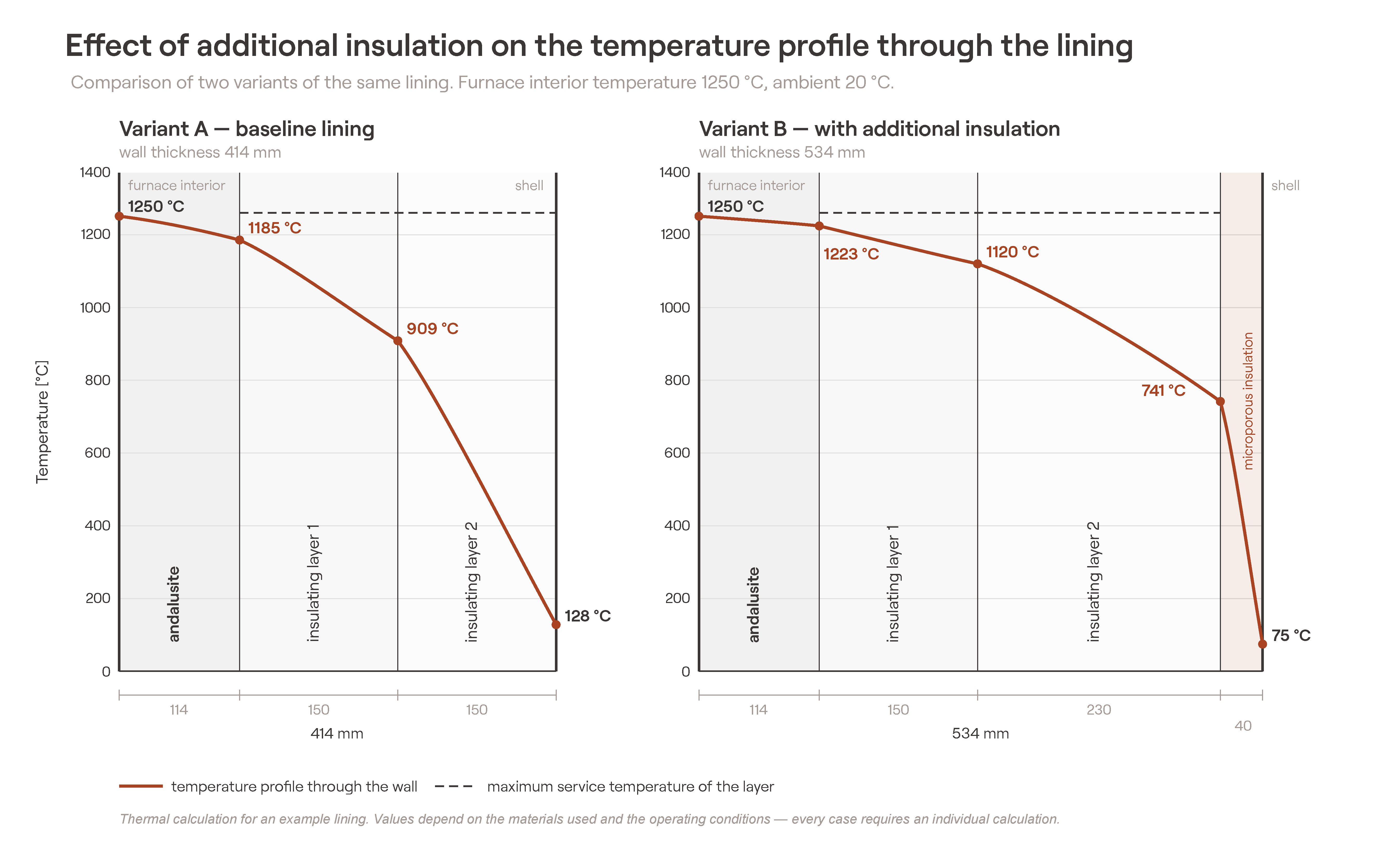
Reducing insulation thickness in critical zones. In zones of extremely high temperatures or intense corrosion, it is preferable to accept higher heat losses than to risk premature destruction of the working lining.
Creating a strong temperature gradient. This can be achieved by deliberately limiting insulation or by applying external cooling (air blast, water jacket).
Zonal cooling of critical spots. In tank furnaces, the lining belts at the glass-line level are often deliberately left without insulation and cooled with air, to weaken corrosion and erosion in this most heavily loaded area.
Techniques for preventing over-insulation
Reduce insulation thickness in critical zones. In zones of extreme temperature or intense corrosion, it’s better to accept higher heat losses than to risk premature working lining destruction.
Engineer a strong temperature gradient. This can be achieved by deliberately limiting insulation or applying external cooling (air blowing, water jacket). A strong gradient keeps the load-bearing outer portion of the wall in an elastic state — providing structural stability to the entire lining.
Zonal cooling of critical locations. In glass tank furnaces, the brick courses at the glass melt line are often deliberately left uninsulated and air-cooled to slow corrosion and erosion in this most heavily loaded area.
Verify temperature limits before installation. Before installing insulation, perform heat transfer calculations to verify that temperatures at the interfaces between layers don’t exceed allowable limits — both for the insulating materials and for the steel shell.
Particular caution when adding insulation to existing furnaces
Adding external insulation to equipment already in operation raises the temperature of all internal layers. This can lead to exceeding the thermal strength of intermediate materials, or cause overheating and creep of the steel structure. This is one of the most common modernisation pitfalls – a seemingly simple modification that can trigger a cascade of problems. That is why, when planning to modify equipment, it is always worth analysing the possible effects of the modernisation with a specialist refractory-lining designer.
Key Takeaways
- Refractory material selection is a systemic process – from the operating conditions audit, through thermomechanical properties and system configuration, all the way to the insulation design.
- Not every zone of a furnace requires the same material – the most heavily exposed areas need premium solutions, while economical materials suffice in less demanding ones. A deliberate choice lets you optimise costs without sacrificing durability.
- Insulation is a double-edged sword: too little = heat loss, too much = accelerated destruction of the working lining.
- Every application is different – a decision framework is a starting point, not a ready-made answer. Consulting an experienced engineer is not an option but a necessity.
Frequently Asked Questions
What is the difference between RUL and plain refractoriness (PCE)?
PCE indicates the softening temperature of a material without load. RUL indicates the temperature at which the material begins to deform under compressive stress – that is, under conditions closer to real operation. In load-bearing zones, RUL is the more reliable parameter.
Why does over-thick insulation shorten lining service life?
Additional insulation raises the temperature of the working layer. This accelerates chemical corrosion, pushes the thermoplastic zone deeper into the lining and – in rotary kilns – hinders the formation of a protective coating. More insulation does not always mean better.
Bricks or refractory castable – which to choose?
This is a system decision, not merely a material one. Bricks offer faster installation and drying; castables offer geometric freedom and fewer joints, but require formwork and careful drying. The choice depends on the geometry of the equipment, the operating conditions, and the available downtime.
How much higher than the operating temperature should a material’s refractoriness be?
A practical rule of thumb points to a margin of around 100–200 ℃ of refractoriness under load (ISO 1893) above the maximum operating temperature. This is a generalisation, however – the furnace atmosphere and the presence of corrosive agents can significantly change the actual requirements.
Need support in selecting refractory materials for a specific application? PCO’s technical team will be glad to discuss the operating conditions of your furnace and propose a solution tailored to your requirements – with no obligation.
Refractory material properties: what CCS, PLC, thermal conductivity and porosity really tell you
Refractory data sheets usually list a similar set of properties: chemical composition, cold crushing strength (CCS), permanent linear change (PLC), thermal conductivity, apparent porosity and bulk density. Engineers compare them in tables, procurement teams use them to rank suppliers, and maintenance departments reach for them when planning repairs.
There is just one problem – these parameters are easily misinterpreted. The temptation to reach for simple generalisations and blanket assumptions is strong. Unfortunately, a higher CCS does not mean a better refractory. A lower porosity is not always an advantage. And a thermal conductivity measured in the laboratory can tell you very little about how the material will actually behave inside your furnace.
In this guide we break down what each of these four key properties actually says about how a refractory performs – and, just as importantly, what it does not say. If you design or maintain refractory linings, understanding these nuances will help you avoid costly mistakes.
Porosity: the property that governs everything else
If you could look at only one number on a data sheet, porosity would tell you the most. That is because it directly influences corrosion resistance, thermal shock behaviour, permeability, thermal conductivity and mechanical strength – in other words, almost every other property that matters in service.
What this number actually means
Apparent porosity (AP) measures the volume of open, interconnected pores as a percentage of the total volume. These are the pores that liquids and gases can enter. The sum of open and closed pores is described by the total porosity.
This distinction matters. Two bricks with identical apparent porosity but different total porosity will behave differently under thermal shock – partly because closed pores arrest cracks without at the same time creating pathways for corrosive infiltration.
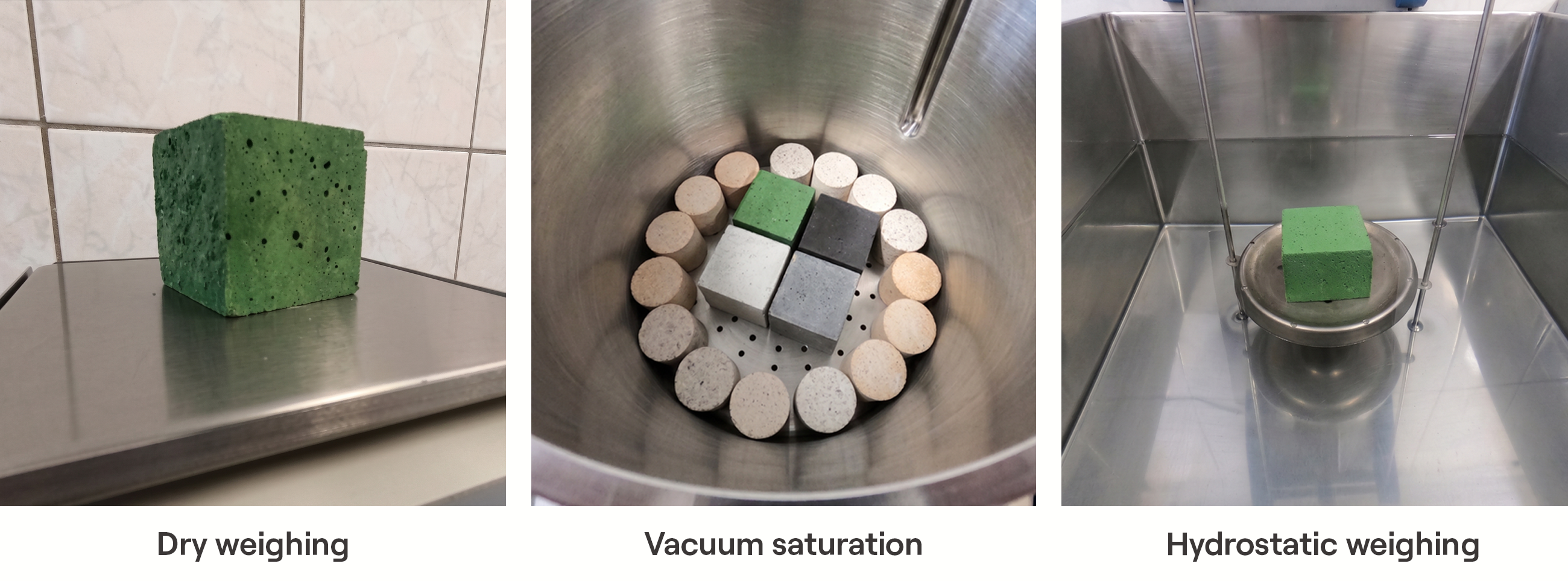
Measurement of apparent porosity by the Archimedes method.
How porosity controls corrosion resistance
Open pores act as flow paths – you can picture them as a network of channels through which molten slag, glass or metal penetrate deep into the refractory. The deeper the penetration, the more destructive the corrosion, because the reactions occur not only at the working surface but throughout the infiltration zone.
But volume alone is not everything. Pore size distribution is equally critical. A material with fine pores (below 1–5 µm) resists infiltration far more effectively than a material with the same total porosity but coarser pores. The reason is capillary pressure – finer pores generate greater resistance to liquid ingress.
The practical consequences are significant. The critical pore diameters below which specific alloys cannot penetrate are approximately:
| Melt type |
Critical pore diameter |
| Steel |
~30 µm |
| Cast iron |
~5 µm |
| Aluminum |
~0.5 µm |
This explains why applications in contact with aluminium require exceptionally fine-pored, low-porosity materials, whereas steelmaking applications tolerate a somewhat coarser structure.
The porosity–thermal shock trade-off
And here it becomes counter-intuitive. Under certain conditions, higher porosity can improve thermal shock resistance – exactly the opposite of what happens with corrosion resistance.
Pores act as crack stoppers through several mechanisms:
Crack-tip blunting. When a propagating microcrack meets a pore, the sharp crack tip – an extreme stress concentrator – is replaced by the rounded surface of the pore. This can drastically reduce the stress intensity and arrest further crack growth.
Crack deflection and branching. Pores force cracks to change direction or split into many smaller branches. Each deflection absorbs additional energy, increasing the material’s effective toughness.
Lower modulus of elasticity. A more porous structure is less rigid. Lower stiffness means lower thermal stresses for a given temperature change – the material can „flex” rather than crack.
Less stored elastic energy. Dense, high-strength refractories store large amounts of elastic strain energy during heating. This stored energy is the driving force behind rapid, destructive crack propagation. Porosity reduces that energy reserve.
It is precisely for this reason that insulating bricks (with 45–85% porosity) are practically immune to thermal shock damage, whereas dense, low-porosity materials can fail catastrophically after a single rapid temperature change.
The design trade-off
Every engineer working with refractories faces the same dilemma: lower porosity for corrosion resistance, or higher porosity for thermal shock resistance? The answer depends entirely on which wear mechanism dominates in your specific application.
In the burning zone of a cement kiln, where the main threat is chemical attack by alkali-rich liquid clinker, you want low porosity. In a steel ladle, which goes through rapid thermal cycles with every tap, you need enough porosity to survive the shock. Getting this trade-off wrong is one of the most common and most expensive mistakes in material selection.
Cold crushing strength (CCS): the most commonly misunderstood number on the data sheet
CCS is the maximum compressive load a refractory sample can withstand at room temperature before it fails. It is also, arguably, the most overvalued property in refractory specification.
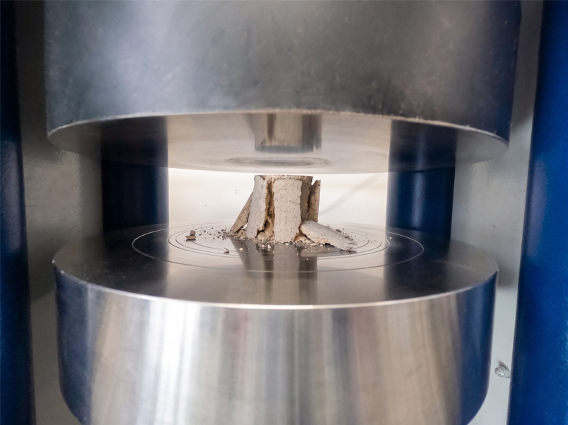
Cold crushing strength (CCS) test.
What CCS actually tells you
CCS is first and foremost a quality-control tool. It indicates whether the material was fired at the right temperature during production, whether sintering proceeded correctly and whether the bonding system (hydraulic, chemical or ceramic) developed as intended.
In other words, it speaks to production consistency. A batch of bricks with CCS significantly below specification probably has a manufacturing problem. That is genuinely valuable information.
Why higher CCS doesn’t mean “better”
A persistent myth lingers in the industry that a refractory with a higher CCS is inherently better. This is misleading, and in some cases the opposite is true.
The fundamental problem: CCS is measured at ambient temperature. A refractory’s working environment is 800 °C, 1200 °C, 1500 °C or more. How a material behaves at room temperature may have little in common with how it behaves at operating temperature.
Specifically:
An excessive CCS may indicate a high glassy-phase content. Glass is strong and rigid at room temperature – which gives impressive CCS values. But glass gradually softens as temperature rises. A refractory rich in glassy phase may show excellent CCS at 20 °C yet deform readily under load at 1100 °C. The result is creep – a slow, irreversible dimensional change under sustained stress at high temperature, which can destroy the lining geometry and close critical clearances.
A very high CCS often correlates with brittleness. Extremely strong, rigid materials have a limited ability to accommodate thermal and mechanical stresses. During cyclic temperature changes they are prone to destructive cracking and spalling rather than controlled microcracking.
CCS says nothing about hot strength. For predicting mechanical performance in service, hot modulus of rupture (HMOR) and refractoriness under load (RUL) are far more informative. HMOR measures flexural strength at the actual operating temperature. RUL measures resistance to deformation under constant load at rising temperature. Both give direct insight into whether the material will retain its structural integrity where it actually matters – inside the furnace, at high temperature.
What CCS is genuinely useful for
CCS reliably predicts whether a refractory will survive the mechanical stresses of transport, handling and installation. A brick needs enough compressive strength to withstand loads on the pallet, forklift impacts and the forces at play during bricklaying. For this purpose, CCS is an appropriate and necessary specification.
Practical takeaway
When reviewing a data sheet, resist the instinct to equate a higher CCS with the material’s mechanical resistance in service. Instead, ask: what are the dominant loads in my specific application – compressive, thermal, chemical? Then look at the properties that directly measure resistance to those loads. CCS tells you whether the material was manufactured correctly. It does not tell you how long your lining will last.
Permanent Linear Change: predicting whether your joints will hold
Permanent linear change (PLC) measures the irreversible dimensional change that occurs after a refractory is heated to a given temperature and cooled back to ambient.
What PLC tells you about production
PLC shows whether the refractory was brought to a stable equilibrium state during production. If a brick was fired at a temperature lower than its target operating temperature, the chemical reactions and sintering processes that did not finish in the manufacturer’s kiln will continue inside your furnace.
This continued reaction means the material is still changing dimensions while it is already in your lining – and once it cools, it will not return to its original size.
PLC is not the same as thermal expansion
This is a critical distinction, and one that even experienced engineers confuse.
Reversible thermal expansion (RTE) is the reversible change in a product’s dimensions caused by rising temperature. It is a purely physical process: atoms vibrate more intensely at higher temperatures, the crystal lattice expands, the material grows. As it cools, it returns to its original dimensions.
Permanent linear change (PLC) describes the change that will be irreversible – the material can either shrink or expand. It is the permanent mark that exposure to high temperature leaves in the material’s structure. PLC results from:
- further sintering and the elimination of pores (causes shrinkage),
- phase transformations and chemical reactions at operating temperature, e.g. the formation of mullite or spinel (can cause expansion or shrinkage depending on the reaction),
- decomposition of binders or the release of gases.
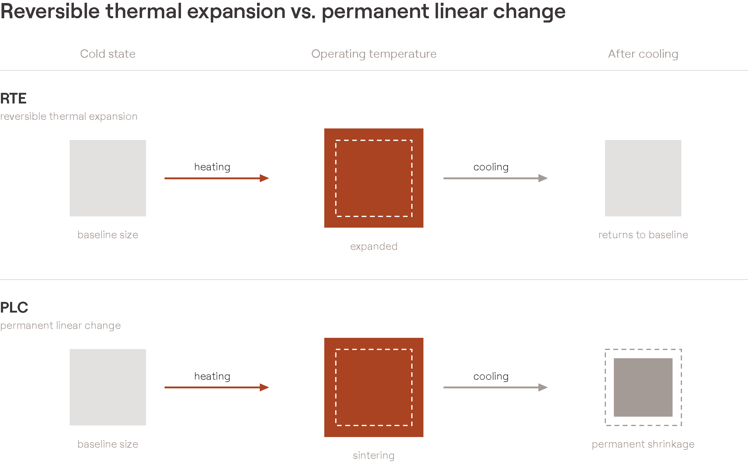
Reversible thermal expansion (RTE) vs. permanent linear change (PLC)
One way to think about it: RTE is the material „breathing” with temperature – it always returns to its starting point. PLC is a permanent change in the material’s „DNA” after exposure to operating conditions.
Why PLC matters for lining integrity
It is worth starting from the fact that permanent shrinkage or expansion is a natural feature of refractory materials. They are not a problem if they occur to a small degree – they can become one when their magnitude is large.
Negative PLC (shrinkage). When a refractory permanently shrinks in service, the joints open up. Open joints allow flames, hot gases or corrosive liquids to bypass the working lining and attack the backup layers or the steel shell. In extreme cases this leads to shell overheating, accelerated degradation of the backup layers and, consequently, unplanned repairs.
Positive PLC (expansion) is sometimes engineered deliberately. In vessel linings such as steel ladles, controlled positive PLC creates a tight clamping ring as the bricks grow slightly during the first heating cycles. This self-tightening effect seals the joints and prevents metal penetration – a critical requirement in steelmaking. Some materials based on „swelling clays” or spinel-forming compositions are specially designed for this purpose.
How PLC affects furnace design
The interplay of RTE and PLC drives several key design decisions:
Expansion joints must accommodate RTE – the reversible thermal „breathing” of the lining during every operating cycle. Undersized joints lead to compressive damage, spalling and, in extreme cases, deformation of the steel shell. Oversized joints, on the other hand, allow hot gases to break through the lining.
Long-term joint integrity depends on PLC. Even if the expansion joints are well designed for RTE, excessive negative PLC will gradually open the working joints over the whole campaign, degrading lining performance over time.
Mortar joints play a compensating role. A properly selected mortar is slightly compressible, absorbing up to half of the reversible thermal expansion of the brickwork. In large-scale structures such as coke oven batteries – where conventional expansion joints are impractical – highly plastic mortars are used to accommodate the full thermal expansion of the wall.
Practical takeaway
When specifying refractories, always check that PLC was measured at a temperature corresponding to your actual operating conditions. PLC data at 1000 °C is useless if your application runs at 1500 °C. And remember – a small, controlled positive PLC can be an advantage in some vessel linings, whereas negative PLC is almost always undesirable.
Thermal Conductivity: the number that changes with everything
Thermal conductivity defines the rate of heat flow through a material. In refractory engineering it determines how effectively a lining works as an insulator (to save energy and protect the shell) or as a conductor (to remove heat and cool the working face).
What this number tells you
At its simplest, thermal conductivity is the basis of every heat balance in furnace design. It determines lining thickness, shell temperature, heat losses and energy consumption. If this value is wrong, the entire thermal design falls apart.
But there is a challenge: thermal conductivity is not a material constant. It changes with temperature, atmosphere and measurement method – sometimes drastically.
How temperature changes everything
Dense and porous refractories respond to temperature in exactly opposite ways:
Dense materials: conductivity decreases as temperature rises. The mechanism is phonon scattering – as atoms vibrate more intensely at higher temperatures, they interfere more strongly with heat conduction through the crystal lattice.
Insulating and lightweight materials: conductivity increases with temperature. At high temperatures, radiation across the large internal pores becomes the dominant heat-transfer mechanism, outweighing conduction through the solid phase that dominates at lower temperatures.
This crossover behaviour means that an insulating material performing well at 600 °C may provide significantly weaker insulation at 1200 °C – a fact that must be taken into account when designing multi-layer linings.
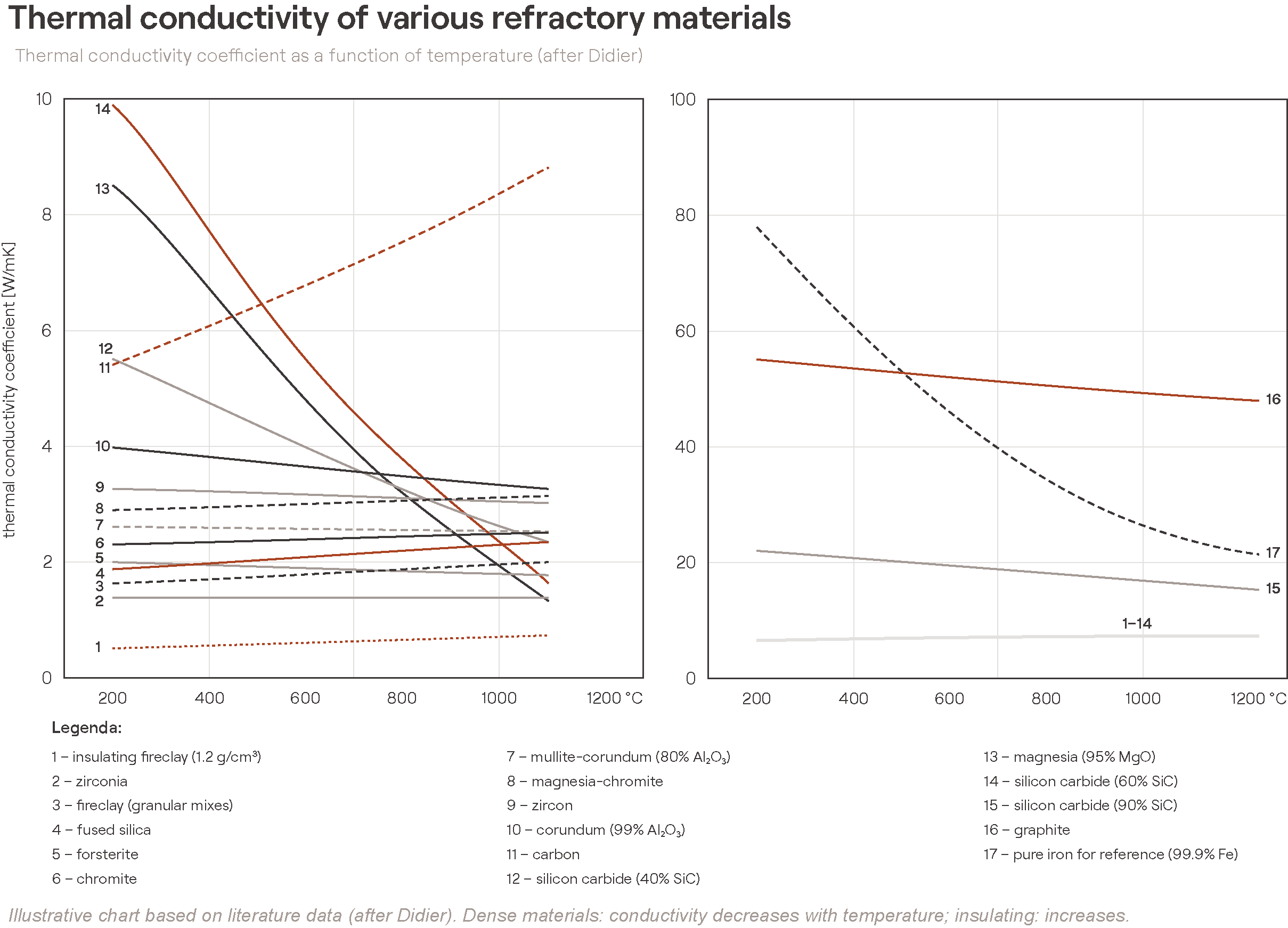
The atmosphere effect that most engineers overlook
Thermal conductivity depends not only on the solid material but also on the gas filling its pores. This is especially significant for porous materials.
An alumina-silicate refractory in a hydrogen atmosphere has a significantly higher thermal conductivity than the same material in air. The thermal conductivity of hydrogen is roughly 7× that of nitrogen. In applications where hydrogen-rich gases are present – some heat-treatment furnaces, direct reduction in steelmaking – standard conductivity data measured in air will significantly underestimate the actual heat losses.
Measuring thermal conductivity – a common pitfall
There are two standard methods for measuring thermal conductivity, and they can give results differing by 15–25%:
| Method |
Operating principle |
Typical use |
| Calorimetric (steady-state) |
Measures heat flow once thermal equilibrium is reached |
Reference method for furnace design; gives an averaged value across the temperature gradient |
| Hot-wire (transient) |
Measures the temperature response to a rapid thermal pulse |
Faster measurement; gives point values at specific temperatures |
The discrepancy stems from fundamental differences in how these methods work. The calorimeter measures conductivity as an average across the temperature gradient inside the sample, whereas the hot wire records the value at a specific temperature. In addition, the hot-wire method conducts heat radially and the calorimeter linearly – for anisotropic materials this yields different results.
In practice, furnace designers usually prefer data from the calorimetric (steady-state) method. When only hot-wire data is available, correction factors of 0.7–0.8 are commonly applied to match design expectations.
Practical consequences for lining design
When specifying refractories for a new lining or assessing insulation effectiveness:
Always check the measurement method. Data sheets do not always state it. If conductivity values look surprisingly low for a dense material, they may come from a steady-state measurement. If they look high for an insulating material, they may come from the hot-wire method.
Use temperature-specific values. A single conductivity figure at 1000 °C is insufficient for a lining with a gradient from 1500 °C at the working face to 150 °C at the shell. Multi-point data across the whole operating range is essential.
Account for the atmosphere. If your process involves reducing gases, hydrogen or water vapour, standard data measured in air may underestimate the actual heat losses.
Consider the ageing effect. Slag infiltration, sintering and chemical reactions during service change the pore structure – and therefore the conductivity. A lining’s thermal behaviour in the first month can differ significantly from its behaviour after a year.
How these four properties interact
No refractory property exists in isolation. The four properties discussed here form an interconnected system, and understanding those connections is what separates effective material selection from data sheet comparison.
Porosity is the common denominator
Porosity directly influences all three of the other properties:
| As porosity increases… |
CCS |
PLC (tendency) |
Thermal conductivity |
| Effect |
Decreases |
Tendency to shrink may increase (more volume to sinter) |
Decreases (better insulation) |
| Gain |
Better thermal shock resistance |
— |
Better energy efficiency |
| Loss |
Lower mechanical strength |
Potential joint instability |
Weaker conductive cooling of the hot face |
The CCS and thermal shock paradox
A very high CCS usually means very low porosity and high stiffness, and both of these factors reduce thermal shock resistance. The strongest material on the shelf may at the same time be the most vulnerable to rapid temperature changes. When cyclic thermal loads are part of the operating reality, a moderate CCS is often the wiser specification.
The interdependence of PLC and conductivity
When a material undergoes a permanent dimensional change in service – whether sintering (shrinkage) or a phase transformation (expansion) – its pore structure changes. Sintering reduces porosity, which increases thermal conductivity. The lining becomes a less effective insulator over time. This is why thermographic data from the first year of a campaign should not be used to predict shell temperature in the third year without accounting for this progression.
Key takeaways
- Porosity is the single most informative property – it can be an indicator of corrosion resistance, thermal shock behaviour and thermal performance. But pore size distribution matters just as much as total pore volume.
- CCS is an indicator of manufacturing quality, not a predictor of in-service performance. A high CCS can signal an excessive glassy phase and brittleness. To assess strength in service, use HMOR and RUL.
- PLC shows whether the material has reached dimensional equilibrium. Always verify that the test temperatures match your operating conditions. Negative PLC opens joints; controlled positive PLC can seal them.
- Thermal conductivity changes with temperature, atmosphere, infiltration and the age of the material – it is never a single, fixed number.
- No property should be evaluated in isolation. Material selection is about finding the right balance between competing requirements – and that balance is different for every application.
Frequently asked questions
Does a higher CCS mean a better refractory?
No. CCS (cold crushing strength) is primarily an indicator of manufacturing quality, measured at room temperature. A very high CCS can in fact signal an excess of glassy phase and brittleness, which worsens thermal shock resistance. HMOR and RUL say far more about how the material performs at high temperature.
What is the difference between apparent and total porosity?
Apparent porosity (AP) covers only the pores that are interconnected and open to the surface – these are what liquids and gases penetrate. Total porosity is the sum of open and closed pores. Two bricks with the same apparent porosity but different total porosity will behave differently under thermal shock, because closed pores arrest cracks.
Why is data-sheet thermal conductivity sometimes misleading?
Because it is not a material constant. It changes with temperature (decreasing in dense materials, increasing in insulating ones), with atmosphere (hydrogen conducts heat about 7× better than nitrogen) and with measurement method (results can differ by 15–25%). A single figure without stated conditions has limited design value.
What is the difference between PLC and thermal expansion?
Thermal expansion (RTE) is reversible – the material grows on heating and returns to size after cooling. PLC (permanent linear change) is irreversible – a permanent shrinkage or expansion that remains in the structure after exposure to high temperature. Expansion joints are designed for RTE, while joint integrity over time depends on PLC.
Need help interpreting the values on a data sheet for your specific application? PCO’s technical team will help you assess a material’s properties in the context of your operating conditions, wear mechanisms and performance goals.